When I first started programming PIC Microcontrollers, I used very crude and simple programmer, JDM type to be precise. It could only program few PICs, and that was all. Its reliability wasn't high, but that didn't discourage me from learning. Long time has passed since then, and I learned a whole bunch. One thing I found out was that there is a much better way how to develop programs for PICs (or any MCU for that matter). The idea of using a reliable, universal in-circuit programmer to speed up my development cycle looked and felt nice. And now I know that I won't have to program PICs the old way.
Inchworm ICD2 is an in-circuit Programmer/Debugger derived from the original Microchip ICD2™ and therefore we can use it as such. One of Inchworm's strongest points is the number of PICs it supports. It can program almost every PIC* which is available on the market (even some PICs that are not on the market yet). This is because the firmware inside Inchworm is field updatable and each new version of MPLAB IDE (which supports ICD2 and thus Inchworm natively) provides such an update. Therefore if you try to program some new PICs unsupported in old version of MPLAB IDE just install newer version, and voilà, now it recognizes and programs the new PIC.
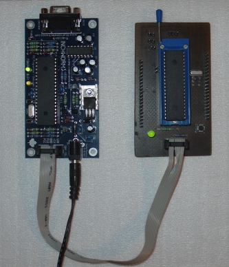
Inchworm unit is very easy to operate. It has three connectors onboard: Female DE9 for RS-232 (Pc connection), DC power connector (9-15V) and finally a 10pin flat cable header connector for the target PIC. There are no adjustable parts, so nothing could be set wrong. Two LEDs inform you of Inchworms status.
Assembly of the Inchworm was straight forward, I followed the instructions published in "Full Assembly Instructions" file located at Inchworms home page. Make sure to prepare all tools and parts as written in the Assembly manual.
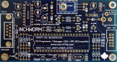
Inchworm PCB is made in nice dark blue color, double sided with solder mask, silk screen and plated thru holes. No wire links are needed. Layout is very good. The only exception being the location of the DC power connector, which I personally don't like to be on the front side (by the target connector). This however does not cause any functional problems.
Start in the center of the PCB with the smallest parts, and work your way to the outside edge(s). It is really easy to place the components in their correct place as the silk screen has part names and positions in place. The solder mask layer ensures that no solder bridges will form so the soldering is even more comfortable.
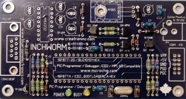
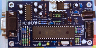
Now you can start to insert and solder all the big parts. When you are about to install the parts, which have a mechanical support (e.g. the DE9 connector or the heat sink) make sure to tighten the mechanical fixing first before soldering the pins to avoid stressing the pin joints. I have also used a tiny drop of glue to better hold the DC power connector in place, just to be sure. At the end, your Inchworm should look like this:
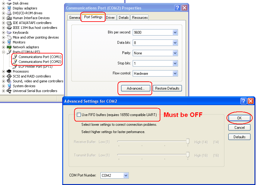
Before we do anything with our freshly built Inchworm, we have to prepare a PC for the use with Inchworm. First thing is to download and Install Microchip MPLAB IDE, a free program. Make sure to install ICD2 plug-in (an option in MPLAB IDE installer). After that is done, you have to turn off FIFO buffers on the COM port you want to connect Inchworm to. Here is a picture how to do that. Restart your computer afterwards. It is very important to do so, or your Inchworm won't work correctly!
Now all needs to be done is to connect the Inchworm to a PC, to the target PIC and attach the power connector. I assume you have your 16F877A part pre-programmed with ICD2_Bootloader_A.hex file (again available at Inchworm's home page). Start MPLAB IDE, "Programmer Menu"/"Select Programmer" and click on "MPLAB IDE". Now MPLAB IDE should try to connect, but it might fail. The reason is that the 16F877A part has only a bootloader installed, so you need to download an OS. So, go to "Programmer menu", click on "Download ICD2 OS". A window will pop-up, select any file available and confirm your selection. After the download is done you can start using your brand new Inchworm!
Inchworm is a very nice looking programmer, that supports almost every PIC*, is easy to build and is very affordable. I consider it as the minimalistic programmer that every beginner should have.
Please visit blueroomelectronics for more information about Inchworm, pricing and availability.
*Due to Inchworms fixed VDD nature, it is unable to program low-voltage devices, such as DsPIC33 and PIC24. This shouldn't be a problem for the beginners as these devices are far more complicated comparing to regular PICs.
| © Jay.slovak 2006 | |
| To contact me, send me a PM (no Help requests please, use Forum for that!) |